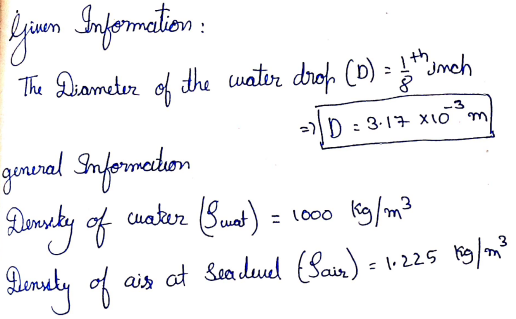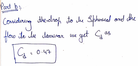
Inspired in the work of van Boxel (1998), Furbish et al. The Uplinger equation is not well suited for the larger drop diameters because the terminal velocity decreases in that region. (1992) have been adopted for the estimation of the kinetic energy of the rain as a function of the intensity ( Salles et al. Several simplified relationships between the raindrop terminal velocity and diameter such as Best (1950), Uplinger (in Ferrier 1994), and Gossard et al. cloud drops (diameters below 0.25 mm) II, small raindrops (diameters between 0.25 and 1 mm) and III, large raindrops (diameters greater than 1 mm). The three classes of drops, slightly modified by Testik and Barros (2007) are: I. Comparison of the Best and Reynolds number computed with the terminal velocity of raindrops of Gunn and Kinzer (1949, Table 1), and the settling velocity of solid particles of Cheng (1997, Table 15.3).īeard (1976) separated the raindrops in three classes attending not only the diameter but the value of the Reynolds number, the ratio between inertial and viscous forces which influences the air resistance to the advance of the falling drop into the atmosphere.

Two explanations for the decrease of particle terminal velocity are: (1) particle shape and (2) rafting within a particle cluster, which reduces the bulk cluster density ( Sorem, 1982 Lane et al., 1993).įig.

Importantly, the (horizontal) fallout distance correlates linearly with the particle residence time, such that the fallout distance will be doubled by halving the terminal velocity. As an example, individual small particles associated with recent eruptions have been observed thousands of kilometers further than expected (eg, Beckett et al., 2015 Stevenson et al., 2015 Part 2), which indicates increased residence times in the atmosphere. The effect of shape on drag coefficient for small particles also has significant implications for the description of particle dispersal in the far range. As an example, if particle shape is approximated as a sphere, particle diameter can be underestimated by up to 20% and 76% for fine ash- and lapilli-sized particles, respectively. Our results also indicate that shape of particles should be taken into account to reliably retrieve the particle size from inversion of in situ velocity measurements (eg, by Doppler-based radar). A factor of two decrease would double the residence time in the atmosphere. This is somewhat less than the fourfold variation observed by direct terminal velocity measurements ( Riley et al., 2003). Additionally, the terminal velocity of the most irregular volcanic particles of any given size is about 50% less than the terminal velocity of volume-equivalent spheres. It can be seen that the effect of shape of volcanic particles on the drag coefficient is almost independent of size ( Fig. 4). Particle shape descriptors f and e were varied logarithmically with size within the ranges shown in Table 1. to assess the overall effect of shape and size on the terminal velocity of volcanic particles ( Fig. 4). These two aspects should be considered together when considering the effect of shape on terminal velocity of volcanic particles. On the other hand, fine ash is less spherical than coarse ash and lapilli, since shape descriptors measured for fine ash are typically smaller (eg, Table 1 Bagheri et al., 2015 Liu et al., 2015). The influence of particle shape on drag coefficient and terminal velocity increases with particle size ( Alfano et al., 2011a Bonadonna and Costa, 2013 Bagheri and Bonadonna, 2015). with one of the drag coefficient models presented above. The terminal velocity of volcanic particles can be found by combining Eq. Bonadonna, in Volcanic Ash, 2016 4.2 Variation of Drag Coefficient and Terminal Velocity With Particle Size Determine the Design Factor (n:) and then determine the design factor ni without axial loading.G. The diameter of the shaft ABC is 1.5 inches. Let (Kr)a = 2.3, (K)b = 2.0 and (K), t = 1.5 where the subscripts a, b, and t represent axial, bending,and torsion, respectively. For the shaft material, Su = 90 kpsi, Sy = 65 kpsi, and has a fully corrected endurance limit of 40kpsi. The bearing at C supports the axial thrust load. Transmitted from the mating gear are tangential, radial, and axial forces F, = 5000 Ibf, F = 58lbf, and F, = 173 Ibf, respectively. Line BG is on the bevel gear extended to the shaft center from point G, the contact point with the mating gear.

#Calculate the velocity of a spherical raindrop free#
For this problem, the free body diagram for a shaft ABC is shown in the figure, where points Aand C are at the bearings. 7-6 Bevel gears transmit torsional, bending, and axial loads to rotating shafts, such as shown in figure13-36.


 0 kommentar(er)
